
You got all your components for your project, so now it’s all about getting it all together. Then it’s great to be able to quickly exchange components and change wiring. That’s where a so-called “breadboard” comes in handy. It’s an easy to use device where you can connect microelectronic components without the need to solder anything.

Breadboard top and bottom (Guhuru, CC0, via Wikimedia Commons); Jumper Cables (Andy Oakley, CC0, via Wikimedia Commons); Assembled circuit on Beadboard (LukeSurl, CC BY-SA 3.0, via Wikimedia Commons)
Breadboards are like pinboards for cables and microelectronics. They present the first step in the design cycle because parts are easily exchanged in case you want or need other components. Within each breadboard, some rows or columns are connected to each other, allowing for easy connection between components. For example, often the slots of the two outside columns (red and blue in the Figure above) are continuously connected. These are great for powering everything, as you only need to connect your power supply once toand can run all power cables from the two columns. In the middle of the board, the sockets are connected in rows of 5-6. You can plug in a microcontroller and connect other components through special breadboard cables (jumper cables). These cables come with either a “Point” or a “Holder” at each end, allowing for versatile connections.

Perfboard (Retired electrician, CC0, via Wikimedia Commons)
Once you got everything working on the breadboard, you are now ready for the next level of the design cycle. As breadboard cables are not very secure and can easily slip out of their sockets, you need something sturdier for deploying your device in the environment: Perfboards. These boards allow you to easily solder your components together and get a secure connection. Here, the rows and columns are no longer connected as with the breadboard, allowing for more compact circuits. Important to mention is that breadboards and perfboards are designed for “throughhole” components, which are microelectronics with small wires or pins that are pushed into beardboards or through the holes of perfboard and then soldered in place.
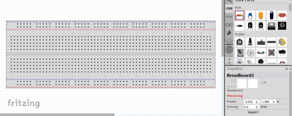
Fritzing GUI empty Breadboard
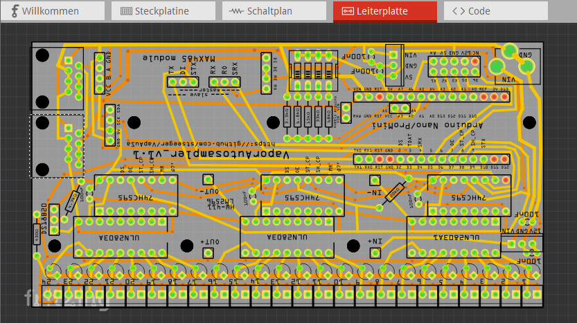
Fritzing routed principal component board

Final assembled principal component board of an autosampler we develope (link to paper) (picture by the author)
Perfboards are great when you don’t need that many devices. But beyond a certain quantity, all the soldering becomes extremely time consuming. What you then need are principal component boards, or short “PCB”. You have probably come across these often-green boards in nearly all our electronics. These are the pinnacle of designing microelectronics. While this might seem too advanced, designing PCBs is just as easy as placing everything on a breadboard, thanks to the open source software Fritzing. There you can place all your components on a virtual breadboard and connect everything with virtual cables. Next, you only need to arrange the components in the editor and let the software auto-connect everything. The generated file can then be uploaded to numerous PCB manufacturers, which produce them at a relatively low cost. When you get your PCB, always use socket terminal strips (picture) instead of directly soldering your component to the board. That way, if a component stops working, you can always exchange it (unsoldering multi-pin components from a PCB is far from fun!). Here you can also use “surface mounted” components, meaning microelectronics which don’t have pins as connectors but rather soldering spots, which can directly be soldered onto the PCB.
Have fun!
This is the last part of this mini-series. Concluding with some advice: always order more components than you think you need, you will destroy some parts during initial testing and that’s fine, it’s part of the learning curve. Even after some years of doing DIY microelectronic projects, I still regularly “smoke” parts (to the point that I now have a trophy wall of all the destroyed components and failed circuits to remind me of the process it takes to develop something). So, don’t hesitate, try stuff and have fun!