Faults and fractures can sometimes be confusing, especially for students taking their first geology courses. When they go hiking in the mountains and see a crack in the rock, they often wonder — is this a fracture or a fault? Even scientists sometimes mix the two terms, so it’s good to understand the difference.
Since faults and fractures are important in many fields such as tunnel engineering, hydrocarbon and mineral exploration, or groundwater studies, it is important to describe carefully what you see.
Start with observable geology
First, when geologists observe a crack in rock, they have several possibilities in mind. They start by thinking in geological terms, based on what can be seen directly. You may see a geologist carefully examining the crack and asking:
– Is there any displacement? If yes, then it’s a fault or a shear fracture.
– If the crack is open with no filling or movement, it’s a joint or fissure.
– If it’s filled with magma that cooled and solidified, it becomes a dike.
– If it’s filled with minerals like calcite or quartz precipitated from fluids, it’s a vein.
– If it shows a zig-zag or serrated shape, it’s called a stylolite, formed by pressure solution.
In consolidated rocks, these are the most common brittle features—faults, joints, veins, and stylolites (Fig. 1). However, in unconsolidated or poorly lithified rocks, such as sand or weakly cemented sandstone, the deformation style is different. Instead of discrete fractures, we often find deformation bands—millimeter-scale tabular zones of localized strain characterized by grain reorganization, cataclasis, and/or dissolution. These bands accommodate strain without forming open cracks and are considered the equivalent of faults and fractures in non-consolidated sediments.
If none of the diagnostic features (displacement, infill type, dissolution teeth) are present, the safest general term is fracture. In short, “fracture” is the umbrella term for brittle breaks in rock, whereas a fault is a fracture that accommodated slip.
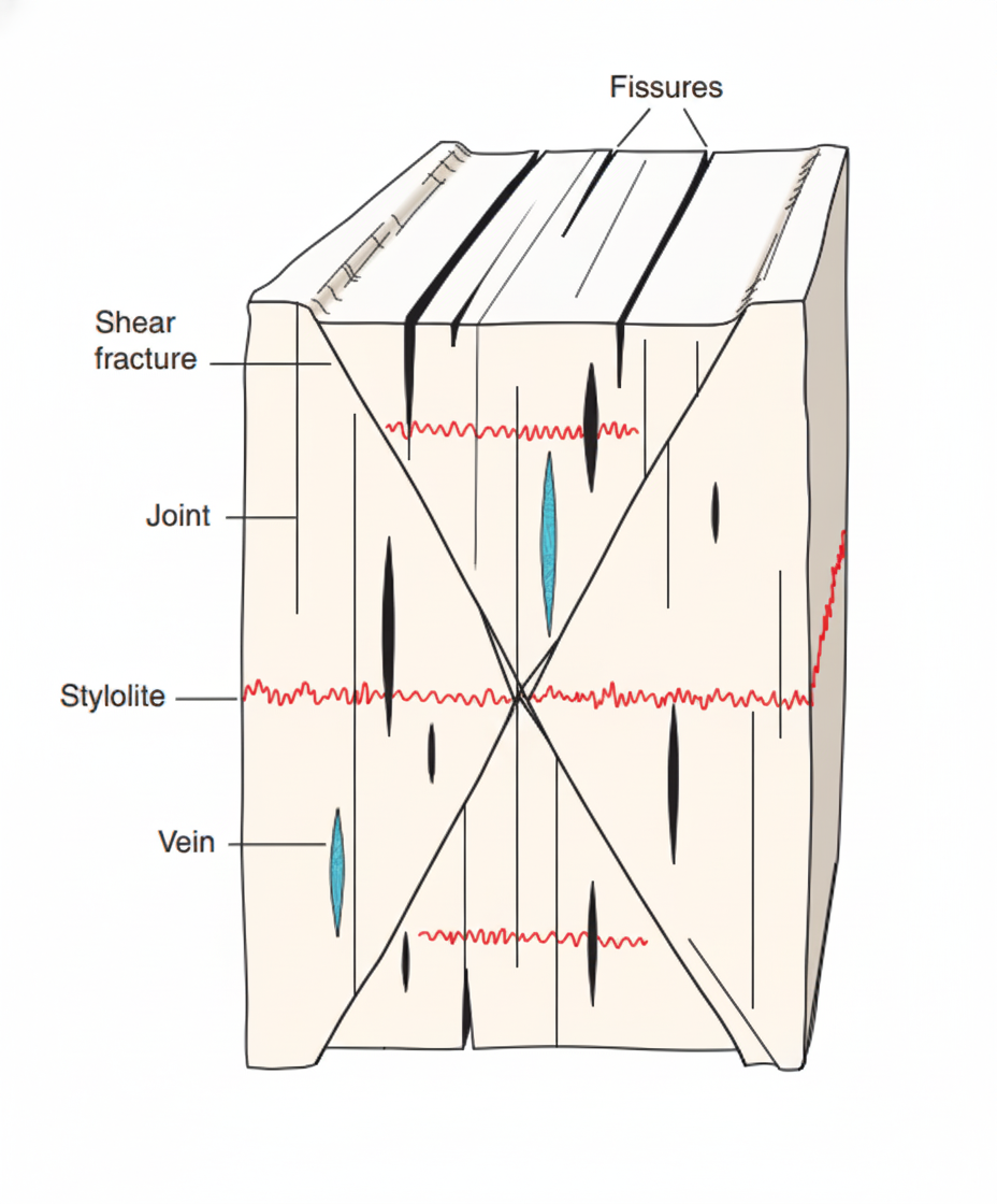
Figure 1: Conceptual diagram of different fracture types,modified from Fossen (2016), Structural Geology, 2nd Edition. This illustration shows how brittle deformation in rocks produces a variety of fractures under stress. Fissures, joints develop perpendicular to the least compressive stress, and veins occur when fractures are filled with mineral precipitates. Stylolites form by pressure dissolution,appearing as jagged red seams, while shear fractures develop diagonally accommodating slip. Together, these features record the stress history of brittle crustal deformation.
Geometrical and topological aspects
To go further, geologists describe the geometry — the fault trace, or segement or branch, the orientation, size, and shape of the fracture. They measure strike and dip (for example, NE–SW fractures), length, and aperture (the opening width). They also look at how fractures are segmented and connected. Overlapping segments form relay structures, and when arranged like a ladder, they are called en-échelon fractures.
Topology captures how fractures intersect (Fig. 2). You may find Y-nodes where one fracture splits into two, I-nodes where one ends against another, and X-nodes where they cross. Mapping node types and branching hierarchy helps quantify connectivity and potential fluid pathways.
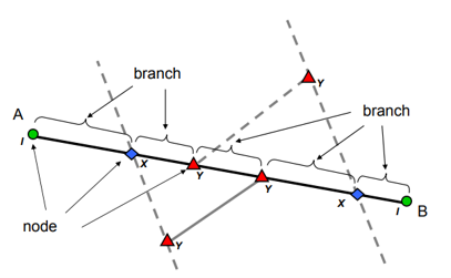
Figure 2: Schematic representation of a fracture trace illustrating the main topological elements: nodes (green circles), branches (black line segments), and intersections (X- and Y-nodes). Modified after Sanderson & Nixon (2015).
Usually, these descriptions are made on surface exposures, but the same logic applies underground. In deeper zones, faults often form complex 3-D patterns like flower structures, where many small faults merge into a main one at depth.
Mechanical aspect — how the fracture formed
Mechanically, fractures can form in three main modes (Fig. 3) depending on the stress field:
-
Mode I (opening mode): the rock is pulled apart, and the crack opens perpendicular to the least stress — this is typical of joints or fissures.
-
Mode II (sliding mode): the crack slides in shear, parallel to its surface, similar to what happens in many faults.
-
Mode III (tearing mode): the crack moves by out-of-plane shear, producing twisting or tearing.
In nature, most fractures are a combination of these — for example, an opening fracture that also slips slightly (Mode I + II). Although not part of the original linear-elastic fracture-mechanics classification, Mode IV has been introduced informally to describe compressional reactivation that closes a pre-existing fracture or joint rather than propagating it.
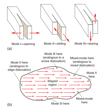
Figure 3: (a) Three fundamental modes of fracture propagation in brittle solids. Mode I involves opening perpendicular to the least principal stress (tensile mode). Mode II involves in-plane shear, causing sliding parallel to the fracture surface and perpendicular to the crack front. Mode III represents out-of-plane shear, producing tearing motion parallel to both the crack front and fracture surface.
(b) Distribution of fracture modes around an irregular slipped region. Mode II (edge dislocation analogue) occurs along the sides, Mode III (screw dislocation analogue) at the ends, and mixed-mode conditions develop where sliding and tearing interact. Together these illustrate that natural faults rarely conform to a single pure mode but instead express combinations of tensile and shear components. Source: Modified from Hatcher, R. D. Jr. & Bailey, C. M. (2020). Structural Geology: Principles, Concepts, and Problems, 3rd ed., Cambridge University Press.
Kinematic aspect — how the blocks moved
Once movement happens along the fracture, it becomes a fault, and we describe it by its kinematics:
-
Normal fault: the hanging wall moves down (extension).
-
Reverse fault: the hanging wall moves up (compression).
-
Strike-slip fault: blocks move horizontally past each other (shear).
-
Oblique fault: a combination of vertical and horizontal movement.
These movements are identified in the field by features such as slickensides, striations, or small drag folds (Fig. 4).
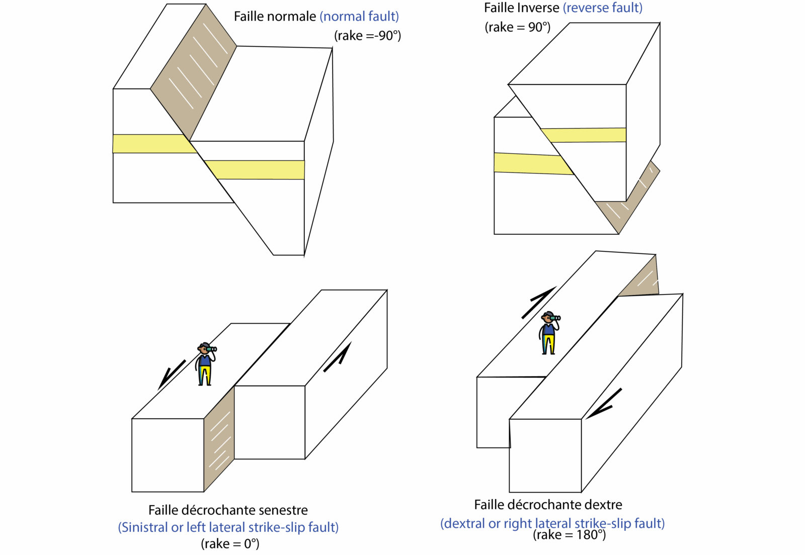
Figure 4: llustration of the four principal fault types classified by their kinematics and slip direction.
(Top left) Normal fault (faille normale, rake = –90°): hanging wall moves downward relative to the footwall under extensional stress.
(Top right) Reverse fault (faille inverse, rake = +90°): hanging wall moves upward relative to the footwall under compressional stress.
(Bottom left) Sinistral strike-slip fault (faille décrochant senestre, rake = 0°): horizontal displacement where the opposite block moves to the left from the observer’s viewpoint.
(Bottom right) Dextral strike-slip fault (faille décrochant dextre, rake = 180°): horizontal displacement where the opposite block moves to the right.
These geometric and kinematic relationships are defined by the rake (pitch) of the slip lineation measured on the fault plane and reflect the orientation of the principal stresses (σ₁, σ₂, σ₃). Source:
Adapted from standard structural geology schematics after Hatcher (2020) and Bailey & Hatcher (2020), Structural Geology: Principles, Concepts, and Problems, Cambridge University Press.
I recommend reading the paper by Peacock et al. (2016) so you can explore in greater depth how to use the correct terminology when describing faults and fractures (Fig. 5). This paper systematically reviews the key terms, supported by extensive references, offering a solid foundation for developing precise and professional geological vocabulary.
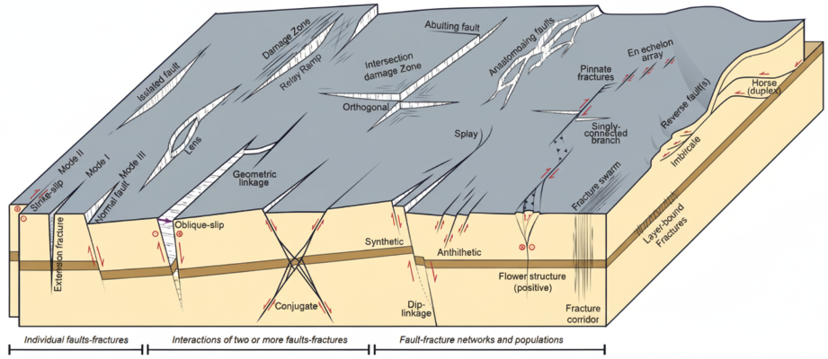
Figure 5 . Schematic illustration showing the range of fault and fracture network types defined by Peacock et al. (2016). The diagram highlights the continuum from individual fractures (e.g., Mode I, II, III faults) to interactions between faults (such as relay ramps, abutting faults, and splay systems) and finally to complex fault–fracture networks (including anastomosing, en échelon, and flower structures). The figure emphasizes standardized terminology for describing brittle deformation structures and their spatial organization.
Key takeaway:
Use fracture as the general term for brittle cracks; call it a fault only when you can have evidence of slip. Then describe orientation, size, aperture, segmentation, intersections, but as an Earth architect, always keep in mind the three-dimensional structural architecture. That consistency makes your observations useful for both science and engineering.