EGU Blogs

Guest Post

Guest Post: Jeremy Bennett – Approaches to modelling heterogeneity in sedimentary deposits

Hello everyone. Great that you could make it out to my blog post. I would like to introduce you to some ideas about environmental modelling that I have recently discovered during my work. These ideas are from this paper by Christine Koltermann and Steven Gorelick back in 1996. Whilst the primary focus of their paper is on modelling hydrogeological properties such as hydraulic conductivity, I think there is crossover with other modelling too.

What I find the most interesting about this work are the words they used to describe modelling approaches, meaning the way the modeller sees the world. They break down modelling into three different approaches: structure-imitating, process-imitating, and descriptive methods. Over the next few mousewheel-scrolls I hope I can explain these ideas in simple terms so that they are easy to understand.

This paper discusses models that are spatially distributed – this means that we are trying to estimate values at different locations in space. In the following diagrams I have simplified things to one dimension to hopefully make things a bit clearer. It is also important to note that many models will combine elements of one or more of the following model approaches – often at different scales.

Descriptive methods

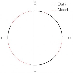
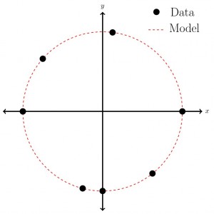
Descriptive modelling approaches are primarily conceptual – kind of like joining the data dots in Figure 1 to produce the circle. There might be no hard and fast rules here, although models may be based on years of experience and observation in the field. These models may not be so rigorous and possibly difficult to replicate in different environments.

desc-1

Fig.1. Descriptive diagram

A good example of descriptive modelling are geological cross sections. They are constructed using borehole data and similar lithologies at similar depths are assumed to be part of the same geological formation. More experienced practitioners will have better intuition for connecting the dots and interpreting the stratigraphic record. In many cases thes cross sections are a suitable model. However in some hydrogeological applications this level of modelling is insufficient as more information is required about the geometry of the formation, and perhaps variations in its hydraulic properties – something that is difficult to derive solely from descriptive methods.

Structure-imitating methods

Structure-imitating modelling approaches quantify observations of the thing to be modelled and use these rules to produce something that looks similar. The structure that is imitated could be the actual shape of the object to be modelled, or it could be something more abstract, such as the geostatistical structure of the observations. To demonstrate: In Figure 2 we have some data shown with black lines. We can then derive information about this data, say in this case the distance of each data point from the centre. From this structural information we can model the rest of the circle.

struc-1

Fig.2. Structure-imitating diagram

A well-known structure-imitating method is kriging. This method uses the geostatistical structure (i.e. mean and covariance) of a set of observations to estimate values of a variable at other locations. A typical criticism of kriging and other geostatistical methods is that defined boundaries between facies become indistinct and don’t look so geologically plausible. Many other methods have been developed, such as multiple-point statistics, to address these arguments.

Process-imitating methods

Process-imitating modelling approaches rely on the governing equations of a process to produce a plausible model. Governing equations describe the physical principles underlying processes such as fluid motion or sediment transport. This type of approach can occur both as forward or inverse modelling. Forward models require setting key parameters in the model (such as hydraulic conductivity) and then predicting an outcome, such as the distribution of groundwater levels. Inverse models start with the observations and try to fit the hydrogeological parameters to the data.

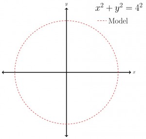
Our final circle model is in Figure 3. In this particular case we know the equation that gives us the circle. As with all process-imitating modelling approaches there is some kind of parameter input required (or forcing). Here we have assumed that the circle is centred about the origin, and our parameter input is the radius of the circle (4) on the right hand side of the equation. Thus we can model the circle based on the equation and a parameter input.

proc-1

Fig.3. Process-imitating diagram

The classic process-imitating model approach in hydrogeology is aquifer model calibration. This is a relatively simple, but widely used, application where zones of hydraulic conductivity are created and adjusted to reproduce measured groundwater levels (hydraulic heads). Often these zones are tweaked using a trial-and-error process to get a better match (or reduce the error). Aquifer model calibration is considered a process-imitating approach because it attempts to replicate the governing equations of fluid flow within porous media. MODFLOW is a model from USGS that is often used in this type of modelling.

Thanks for making it all the way down here. My aim was to provide you with a couple of new words to describe modelling approaches in geosciences and beyond. If you are working in hydrogeology then this paper by Koltermann and Gorelick is definitely worth a read – it gives an excellent foot-in-the-door to hydrogeological modelling.

Reference

Koltermann, C. E., and Gorelick, S. M. (1996). Heterogeneity in Sedimentary Deposits: A Review of Structure-Imitating, Process-Imitating, and Descriptive Approaches. Water Resources Research, 32(9), pp.2617-2658.

About Jeremy CVpic

Jeremy Bennett is conducting doctoral research at the University of Tübingen, Germany. He is researching flow and transport modelling in heterogeneous porous media. Prior to his post-graduate studies in Germany he worked in environmental consultancies in Australia and New Zealand. Jeremy figures there is no better way to understand a concept than to explain it to others – hopefully this hypothesis proves true. Tweets as @driftingtides and blogs here.

Guest Post: Dr. John W. Jamieson – Using seafloor mapping to find missing Malaysia Airlines flight MH 370

Guest Post: Dr. John W. Jamieson – Using seafloor mapping to find missing Malaysia Airlines flight MH 370

On March 8th, 2014, Malaysia Airlines flight MH370 disappeared while en route from Kuala Lumpur to Beijing.  Evidence from satellite tracking suggests that the aircraft may have crashed into the Indian Ocean several 1,000 kms west of Australia and this is where the search is now focused.  No debris or oil slick related to the aircraft has so far been found.  However, signals consistent with the “pings” of the flight data recorder were detected in two areas, several 100 kms apart from each other.  A search of the northernmost location, using an autonomous underwater vehicle (AUV) owned and operated by the United States Navy has so far turned up no sign of wreckage of the aircraft.  The intent of this blog post is to explain what instruments are being used to locate the wreckage, how they work, what are their limitations, and hopefully provide some clarity and perspective on the monumentally difficult task that lies ahead for the searchers.

Why is finding something on the seafloor so difficult?  The methods we use for mapping and surveying on dry land (e.g., aerial photographs, satellite imagery, laser and radar mapping) rely on the electromagnetic spectrum (e.g., radio frequencies, the visible spectrum and even infrared photography).  Electromagnetic waves attenuate quickly in seawater, however, and can only propagate over short distances (sunlight only penetrates the top 200 m of the ocean, known as the photic zone).  The result is is that we cannot see through water very well using electromagnetic waves, and the oceans effectively shield us from surveying the seafloor using traditional means used on land (and on other planets!).  So, to map the seafloor, alternative techniques are required.

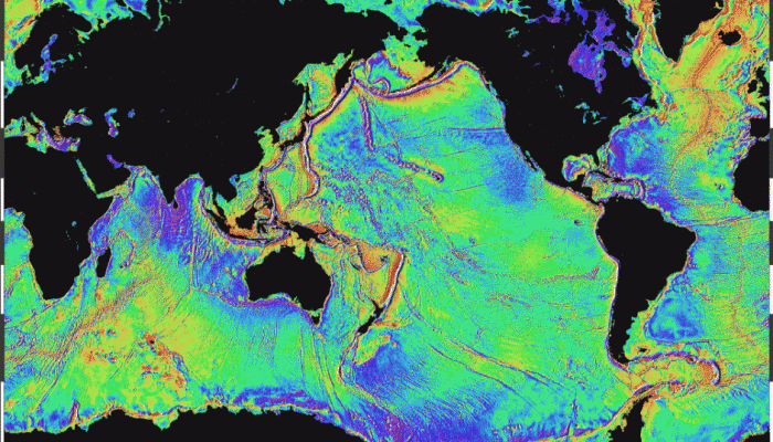
On any world map that includes information on the ocean floor (e.g., Google EarthTM) you can see features such as ridges, seamounts, the continental shelves and submarine trenches.  These features were mapped using satellite altimetry, a technique in which orbiting satellites use radar to measure small spatial variations in sea level.  The uneven surface of the ocean results from variations in Earth’s gravitational field, which is stronger above positive features (e.g., a volcano) on the seafloor, due to the presence of more mass, relative to regular abyssal plain.  The increased gravitational pull causes seawater to preferentially flow to that location, resulting in an elevated ocean surface height directly above the volcano, or a dip in ocean surface height above a trench.  These sea surface variations can be translated into a map of topographic features on the seafloor (Fig. 1).  The resolution of the map, however, is only 1-3 km, which means features on the seafloor smaller than a few kilometers cannot be resolved (note that most media outlets covering the Malaysia Airlines search have been inaccurately reporting the resolution as 20 km).

Figure 1: Global seafloor topography map derived from satellite altimetry data.  Source: http://topex.ucsd.edu/WWW_html/mar_grav.html

Figure 1: Global seafloor topography map derived from satellite altimetry data. Source: http://topex.ucsd.edu/WWW_html/mar_grav.html

To generate maps of the seafloor with higher resolution, hydroacoustic or SONAR (Sound Navigation And Ranging) methods are used.  Unlike visible light or radio waves, sound waves are compression waves and can travel greater distances in water, and hydroacoustic techniques (e.g., the “pinging” of a flight data recorder) are the standard methods used for underwater mapping and communication.  Multibeam sonar is a mapping technique where a series of acoustic beams are emitted simultaneously downward to the seafloor in a fan-shaped geometry perpendicular to the direction of travel of a ship, submarine or other carrier platform.  The time taken for the acoustic signals to reflect off the seafloor back to a receiver is converted into a depth.  By using multiple beams, a swath underneath the ship that is roughly equally to 2 to 7 times the depth can be mapped, producing a 3-D topographic image of the seafloor beneath a vessel as it moves forward.  Modern multibeam systems can produce maps with a resolution of ~30 m (actual resolution is dependent on several parameters including depth and speed of the vessel).  It would take a fleet of 10 ships 15 to 45 years of continuous surveying to map the entire ocean floor at a resolution of ~40 m.  Although the resolution of multibeam mapping is significantly higher than the global satellite map, it is still inadequate to be of any use for finding a downed aircraft.

Higher resolution maps can be generated if the multibeam transmitter and receiver are closer to the seafloor.  This is achieved by mounting multibeam systems onto instruments towed deep beneath a ship by a cable, or, more recently, using AUVs such as the U.S. Navy’s Bluefin-21, which are effectively underwater drones that can be programmed to fly at prescribed altitudes above the seafloor.  From heights of 50-100 m above the seafloor, resolutions of less than 1 m can be achieved, which is good enough to find objects on the seafloor such as sunken ships, containers that have fallen off cargo ships, or aircraft wreckage (Fig. 2).

Figure 2: Example of a 2 m resolution image of the seafloor, derived from autonomous underwater vehicle (AUV) multi-beam SONAR data.  This image is from the Juan de Fuca Ridge, in the NE Pacific Ocean. The mound in the foreground has a diameter of ~75m and a height of 26 m.

Figure 2: Example of a 2 m resolution image of the seafloor, derived from autonomous underwater vehicle (AUV) multi-beam SONAR data. This image is from the Juan de Fuca Ridge, in the NE Pacific Ocean. The mound in the foreground has a diameter of ~75m and a height of 26 m.

A related hydroacoustic method that is commonly used (including for the Malaysia Airlines search) is side scan sonar.  Instead of emitting acoustic beams downwards, beams are emitted outward and downward at a wider angle, relative to multibeam sonar.  The intensity of the reflected signal is measured, producing an acoustic “image” of the seafloor.  The advantage of side scan sonar is that hard, solid objects stand out clearly, and, because the survey “swath” is wider than that for a multibeam survey, a larger area can be covered.

The initial search area for MH370 was a 314 km2 area where a pinging consistent with that of the Boeing 777’s black box was detected.  This area was surveyed with a U.S. Navy Bluefin-21 AUV using side-scan sonar, covering an area of ~40 km2 per day.  This initial survey turned up no evidence of the missing aircraft.  As the search radius expands, the area of seafloor to be covered increases exponentially.  For example, expanding the survey area to cover 60,000 km2 of seafloor, which is likely the next step, would take over two years with a single AUV.  However, this area will first be mapped using ship-based multibeam (a process that has already started), before choosing new targets to survey more thoroughly with an AUV.

In 2009, Air France flight AF447 crashed in the Atlantic Ocean en route from Rio de Janeiro to Paris. The wreckage of the aircraft, including the flight data recorder, was found two years later after searching nearly 17,000 km2 with 3 REMUS6000-type AUVs (one from GEOMAR in Kiel, Germany, and two from Woods Hole Oceanographic Institution, in Massachusetts, USA).  Figure 3 shows side scan reflections that were the first images of wreckage on the seafloor from the Air France flight.  Luckily, the wreckage came to rest in a flat, featureless area within a very mountainous region of seafloor near the Mid-Atlantic Ridge, so that the reflections seen in the image stood out easily.  Had the wreckage come to rest in an area such as that shown in Figure 2, the wreckage would not necessarily stand out so clearly.

Figure 3:  Side scan image of initial discovery of Air France 447.  The debris appears as bright reflections on an otherwise flat seafloor.  Source: http://www.bea.aero/docspa/2009/f-cp090601e3.en/pdf/f-cp090601e3.en.pdf

Figure 3: Side scan image of initial discovery of Air France 447. The debris appears as bright reflections on an otherwise flat seafloor. Source: http://www.bea.aero/docspa/2009/f-cp090601e3.en/pdf/f-cp090601e3.en.pdf

A major difference with the Air France search, compared to the Malaysia Airlines search, is that floating debris was discovered within a week of the crash, providing searchers a clear target from which to base their search.  The current search location in the Indian Ocean is constrained by satellite data, which defines a broad area spanning 1,000s of kms, and two separate reports of potential acoustic flight recorder pings, spaced 100 kms from each other.  With no physical sign of any wreckage, this search is indeed daunting and may take many years.


About the author:

John Jamieson is a research scientist at GEOMAR – Helmholtz Centre for Ocean Research, in Kiel, Germany.  John obtained his B.Sc. in geology from the University of Alberta in 2002, his M.Sc. in isotope geochemistry from the University of Maryland in 2005, and his Ph.D. in marine geology from the University of Ottawa in 2013.  John specializes in the study of mineral deposits that form at hydrothermal vents (or “black smokers”) on the seafloor, and the development of technology and methods for submarine exploration.  His research has led to participation on several research cruises and projects in the Pacific, Atlantic and Indian Oceans.  He has twice dived in the ALVIN submersible on the Juan de Fuca Ridge in the NW Pacific to depths of over 2,000 m.  His research currently focuses on the use of autonomous and remotely-operated vehicles and their mapping capabilities to locate and understand the geological controls on the formation of mineral deposits on mid-ocean ridges.  He works with governments, international organizations and industry on aspects related to seafloor mining.

The author, on board the French research vessel Pourquoi Pas?, with the GEOMAR REMUS6000-class AUV “Abyss” which was used in the search for the Air France flight AF447 wreckage.

The author, on board the French research vessel Pourquoi Pas?, with the GEOMAR REMUS6000-class AUV “Abyss” which was used in the search for the Air France flight AF447 wreckage.

Guest Post: Hilary Dugan – Ice as a platform for understanding lake ecosystems

Guest Post: Hilary Dugan – Ice as a platform for understanding lake ecosystems

Today we have a new guest post written by current PhD candidate and Antarctic researcher on her very fascinating field work. Actually, she wrote this post while at McMurdo station. Hilary and I have known each other since our time at Queens University in Kingston, when she was one of my TA’s and was doing her masters. For more info about her work see the bio at the end of the post at check out her own excellent blog.

In Antarctica, there is a small swath of land hidden by the Transantarctic Mountains that is too dry and sheltered to be overridden by the ice sheets that cover over 99% of the continent. In these barren valleys, life is at the edge of existence and sustained by pulses of meltwater that form when summer temperatures finally break the freezing point. The only refuges of perennial water in this habitat are the large lakes that occupy the topographic depressions in the valley bottoms. The lakes themselves are hidden beneath permanent ice covers of 4 m, but reach depths of 20 to 75 m, and temperatures of -13 degC to +25 degC. As a colleague remarked, “This system of valleys is one of the coldest and driest places in the world and has more in common with Mars than it does with your backyard”.

1

Don Jon Pond (the saltiest body of water on Earth) in Wright Valley, Antarctica

The McMurdo Dry Valleys is also one of the only places in the world with year-round lake ice, which is partly why I spend a few months of the year hidden beneath a giant red parka. Imagine studying the atmosphere without solid ground. Where would we build telescopes, satellite dishes, or research stations? In oceanography and limnology, this is a fundamental roadblock in the collection of long-term data, and is amplified in remote and deep environments where ships or divers can be logistically impossible to send.

2

Downloading datalogger at Lake Fryxell, Antarctica

Luckily for polar researchers (and everyone else *), the solidification of water into ice happens at relatively warm temperatures (0 degC for freshwater, -1.9 degC for ocean water) and floats, thereby providing a frozen platform to access the hidden ecosystem beneath. In most temperate environments, this advantage is limited to a few winter months, and in the shoulder seasons, ice is viewed as a destructive force capable of destroying or dragging around all but the sturdiest of instrumentation. The result is most high-resolution lake data is acquired from spring to fall before buoys are pulled for the winter. Ice is both a boon and a barrier for limnology.

3

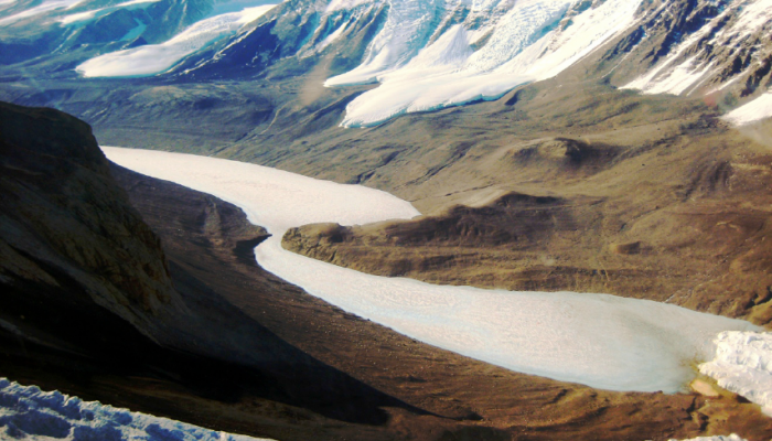
Lake Bonney, Antarctica. Blood Falls can be seen at the edge of Taylor Glacier in the lower right hand corner.

The permanent ice covers in the Dry Valleys allow us to moor instrumentation beneath the ice cover year round, which is a rarity in limnology. Below 4 m of ice, we record physical parameters, such as ice thickness, underwater radiation, ice ablation, and lake level. Our research is primarily focused in Taylor Valley, which has been an US National Science Foundation LTER (Long Term Ecological Research) site for the past twenty years. Three large closed-basin lakes span a range of physical conditions, and represent some of the saltiest and coldest bodies of water on Earth. Because the lakes harbor liquid water year-round, the lakes may be the microbial Amazon of the Dry Valleys; even though the ecosystem is made up of a simple trophic structure. This simplicity allows biological processes and interactions to be more easily studied than in more biologically complex habitats.

4

Surface dataloggers at Lake Hoare, Antarctica

This long-term data allows us to track the habitability of lakes, and general hydrology of the watershed. For instance, the last decade has seen a tremendous rise in lake levels, and therefore a positive water balance in the Valleys. This has come without a concomitant increase in temperature, and researchers are currently investigating the trigger for meltwater production in this water-starved environment.

5

In our goal of year-round monitoring, one major hurdle is that biologic sampling is only conducted during the summer, when the temperatures are reasonable enough for personnel to be in the field. Therefore, any assumptions of microbial activity during the polar winter have been extrapolated from data procured mainly from Oct to Jan (one very cold season stretched until April).

This field season, our goal was to fill in the missing months, and for the first time understand ecosystem functioning during a period of total darkness; a subject extremely valuable to those studying the habitability of environments outside our planet. Instead of over-wintering in Antarctica (we’re not that crazy), we moored three large automated instruments in Lake Bonney: a water sampler, a phytoplankton sampler, and a profiling CTD equipped with a fluorometer and CO2, dissolved oxygen, and PAR sensors. These instruments will be collecting data and samples until our return in Nov. 2014.

6

Deployment of an automated phytoplankton sampler in Lake Bonney, Antarctica.
Pictured: Luke Winslow (University of Wisconsin, Madison), Kyle Cronin and Dr. Peter Doran (University of Illinois, Chicago)

This winter it will be 40 years since the New Zealand program’s last overwinter campaign in Wright Valley. While they braved complete darkness and colder temperatures than most of us have ever experienced in the pursuit of meteorological measurements, I will be nestled warmly in Chicago knowing that somewhere far away a CTD will be capturing the first winter data from one of the most unique lakes on the planet.

As otherworldly as Antarctica may seem, the life that exists in this frozen corner of the Earth demonstrates the incredible adaptation of organisms to surrounding environments, and is likely the closet planetary analogue to any life that may exist on other icy planets in our solar system. Perhaps one day in the future, some young scientist will be making the same comments about their research beneath the icy shell of Europa.

* – If ice was denser than water (like the solid form of most liquids) the ocean would freeze from the bottom up, drastically changing ocean circulation and climate.


I am a PhD candidate at the University of Illinois at Chicago, working with Dr. Peter Doran in the Department of Earth and Environmental Sciences. My current research focus is on Antarctic limnology, with the overarching hypothesis that small variations in climatic conditions can result in extreme hydrologic shifts. I am actively involved in three Antarctic projects: one which examines the hydrology and microbiology of a unique lake with a 27+ m ice cover, a second which uses geophysical techniques to map subsurface brines beneath lakes, and a third which focuses on long term limnological changes as part of the McMurdo Dry Valleys Long Term Ecological Research (LTER) program.

7

One of my responsibilities is to maintain long-term data sets associated with the physical properties of the McMurdo LTER lakes. This includes field-based implementation of lake stations, upkeep of instrumentation, data compilation and management, and ultimately, analysis of the data sets. I regularly employ analytical tools, such as R, Matlab, and ArcGIS, to both to post-process data and explore spatial imagery.

For more information, feel free to visit: https://sites.google.com/site/hilarydugan/
Or check out my field blog at: http://b511m.wordpress.com/

Guest Post – Mike Power – Using surficial geochemistry to detect buried mineral deposits

Finding the next big mineral deposit is a dream of many geologists past, present and future. However, in the past hundred years or so, many of them close to surface have already been found and developed. This is because they can be found relatively inexpensively by traditional methods such as geochemical surveys, shallow geophysics, drilling, and a lot of luck. In the 21st century, mineral exploration is focussing on methods to find deeply buried mineral deposits, ones that can lie almost 800m beneath the surface!

To develop new methods for finding such deposits, I travelled up to northern Saskatchewan, Canada, to the Athabasca Basin, which is home to the world’s highest grade uranium deposits. As part of my M.Sc. thesis at the University of Ottawa, I completed surficial geochemistry surveys above two different uranium (U) deposits – one (Phoenix) of which is “unconformity-related”, which means it lies between the Paleoproterozoic Basin and underlying Proterozoic basement rocks at 400 m depth below the surface. The other (Millennium) is a “basement-hosted” deposit, which means it lies entirely in these basement rocks at nearly 750 m depth. When I say surficial survey, I mean taking materials from the surface or near-surface environment – soils, tills, water, gas, and sandstone, and testing them with various geochemical methods to see if we can detect signatures possibly related to the U deposits beneath (fieldwork photo, Figure 1). For soils, sandstones & tills, we used total and partial digestion with various acids to leach out what is considered the “mobile” trace metal fraction that may have migrated from an ore deposit to the soil. For water, we looked at trace metals and also tritium, a known decay product of U. For gases, we looked for dissolved gas (helium) in water-filled drill holes, as this is also a known decay product of U and its daughter products.

Fieldwork

Fig. 1: Here I am sampling above the Phoenix uranium deposit in September 2011, holding an auger with the various soil horizons we collected for sampling.

At the Phoenix survey site in 2011 & again in 2012, we discovered distinct metal anomalies in soil, till and sandstone (both humus, the organic-rich top fraction you might find in your local forest, and in B-horizon, the rich, brown soil a foot or so deeper) for U – but also Pb, Ni, Cu, Co, Mo, W, and Ag in these media (see Fig. 2a & 2b). Many of these elements are what are considered “pathfinder” metals for U, so will be enriched in the deposit itself or behave in a similar geochemical manner. Geochemical anomalies (high values) only exist when compared to background values that are low, whether a background station, or the mean + 2 σ (standard deviations) of each metal population, so any we considered had to meet this threshold.  We found these anomalies directly above the deposit itself, and also above the location of a major ore-hosting fault, using a “transect” sampling method, or taking samples in a line across a targer. This allowed us to survey across the surface trace of the deposit perpendicular to the direction of the last major ice flow event, so this would not affect our results, or “smear” metals occurrences down-ice.

Untitled

Fig. 2a: Contoured geochemical results for U in aqua regia digestion of humus soil samples from 2011-2012 and partial leach of the uppermost sandstones of the Manitou Falls Formation. The sandstone map showing interpolated U abundance from partial leach in were used as an independent base on which the soil transect results from aqua regia digestion were plotted. The surface traces of Zones A and B1 are also outlined for reference.

U Resampling GEEA_edited

Fig 2b: Detailed 2012 humus soil sampling near the 2011 site (PHX028, furthest left on graph) that showed the highest U value. The results, (samples PHX231-237 & background measurement in 2012) confirm the reproducibility of anomalous U observed last year.

Based on the results we obtained at Phoenix, we decided to see if we could detect any anomalies in these materials that might be related to Millennium- the much deeper deposit. Using leaches on the humus and B-horizon soils, we were also able to see anomalies of U, Pb, Ni and Cu, which was encouraging, as these occurred over the deposit, and also over the surface projection of the ore-hosting fault, which was interpreted to come to surface based on a 3D seismic geophysics survey. Even more exciting, at this site, however, is that we obtained values of 4He (the main isotope of He) that were more than 700 times atmosphere in drill holes intersecting the deposit (Fig. 3)! (Ed Note: 4He is a product of uranium decay – the alpha particles that Uranium emits as it decays are, in fact, 4He nuclei. Therefore, an anomalously high 4He value is a good indicator of nearby Uranium decay.) It was important that in drill holes that weren’t near the deposit, we did observe atmosphere values, as to have a good measurement of background. Having anomalies in trace metals in the soils was one thing, but now we observed gas anomalies in water in the same locations. This led us to conclude that there was a high possible of redistribution and upward migration of U ore related metals and decay products from the deposit at depth.

Fig 10 (1)

Fig 3: Ratios of 4He/36Ar in the sample and 4He/36Ar in the calculated value for air-saturated water (ASW) vs. the inverse value of the abundance of 4He in each sample. Three samples (MLN G05-07) display extremely radiogenic values of 4He, while the typical atmosphere value is plotted (as a 4He/36Ar ratio of 1). The radiogenic 4He observed could possibly be sourced from the U deposit at depth

Now that we had our hypothesis of upward migration of metals (Phoenix) and both metals & gases (Millennium), could we guess if these processes are happening in modern times, or happened long ago? When we look at lead isotopes in humus at Phoenix, we observed that they show what is know as a common lead signature – which means lead not related to radiogenic, or radioactive, lead associated with active uranium decay. Therefore, we assume that this system is closed and metals have not migrated in many thousands (or millions) of years. At Millennium, however, we observe radiogenic He levels in modern-day groundwaters above the deposit, suggesting these products are actively migrating away from the deposit. So some deposits are closed at present day, and some are open. It just depends how you look at them!

That the geochemistry of surficial materials can be used to explore for deeply buried mineral deposits is a powerful idea, and much work still needs to be done depending on the deposit type and surficial environment being explored in. It is cheaper compared to geophysics and radiometrics, and can be completed with a relatively smaller crew of just a few people. And just like other techniques, it isn’t always going to find the next big deposit, but can be another useful instrument in the explorationist’s toolbox.


IMG_6579

Michael Power is an MSc student in exploration geochemistry at the University of Ottawa in Ottawa, Canada. He did his undergraduate degree at Memorial University in Newfoundland, Canada. Michael has worked in a range of mineral and petroleum exploration related positions during and after his undergrad, from the oil sands of Alberta to the gold districts and offshore oil fields in Newfoundland. His MSc research is trying to better understand how geochemistry of surface materials can detect deeply buried U deposits. Tweets as @mikeyp22